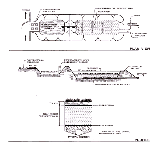
Stormwater Design Example: Sand Filter

SANDFILTER DESIGN EXAMPLE
This example describes in detail the design of a sand filter to treat stormwater runoff from the Brown Civic Center (Figure 1). The filter must meet the following design criteria:
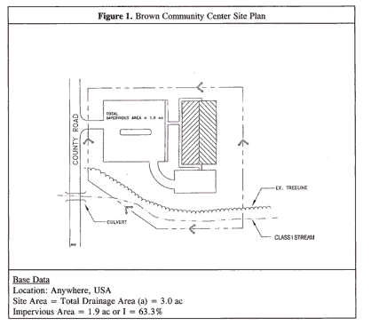

Site Specific Data:
Existing ground elevation at BMP location is 22.0 feet, mean sea level. Soil boring observations reveal that the seasonally high water table is at 13.0 feet. Adjacent creek invert is at 12.0'. Hydrology analyses results are in Table 1.
Step1. Compute Water Quality Volume:
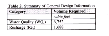
WQv previously determined to be 6,752 cubic feet (Table 2).
Step 2. Determine available head (See Figure 2).
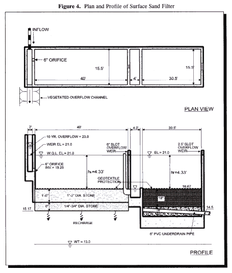
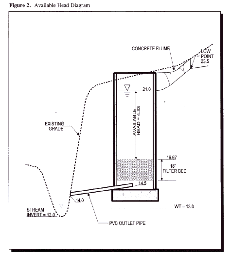
Low point at parking lot is 23.5'. Subtract 2' to pass Q10 discharge (21.5) and a half foot for channel to facility (21.0). Low point at stream invert is 12.0'. Set outfall underdrain pipe 2' above stream invert and add 0.5' to this value for drain (14.5). Add to this value 8" for the gravel blanket over the underdrains, and 18" for the sand bed (16.67). The total available head is 21.0 - 16.67 or 4.33 feet. Therefore, the allowable depth (2) (hf) = 4.33', and hf = 2.17'.
Step 3. Compute Recharge Volume:
This surface sand filter design will have an "open bottom" sedimentation basin to allow ground water recharge. The exact dimensions will be sized later, but the volume stored within the sediment chamber must at least be 1,688 cubic feet.
Step 4. Compute WQv peak discharge (qp):
Compute modified CN for 1" rainfall (Note: In this example the WQv corresponds to the runoff from a 1" storm.)
P = 1.0"
Q = 0.62"
CN = 1000/[10+5P+10Q-10(Q2+1.25*Q*P)�]
= 1000/[10+5*1.0+10*0.62-10(0.622+1.25*0.62*1.0)�]
= 95.6
Use CN = 96
For CN = 96 and the Tc = 0.16 hours, compute the qp for a 1" storm. With the CN = 96, a 1.0" storm will produce 0.62" of runoff. From TR-55, Chapter 4, Ia = 0.083, therefore I a/P = 0.083/1.0 = 0.083. From Exhibit 4 - II (page 4-6 of TR-55), q u = 900 csm/in, and therefore qp = (900 csm/in) (0.62") (3.0 ac/640ac/sq mi.) = 2.6 cfs.
![]() The
modified curve number approach adjusts for the fact that TR-55 typically underpredicts
the runoff from small storm events. The curve number is calculated based on
the runoff volume calculated in the "Sizing Options Design Example".
The
modified curve number approach adjusts for the fact that TR-55 typically underpredicts
the runoff from small storm events. The curve number is calculated based on
the runoff volume calculated in the "Sizing Options Design Example".
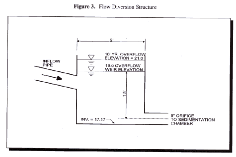
Step 5. Size flow diversion structure (see Figure 3):
Size a low flow orifice to pass 2.6 cfs with 1.5' of head using the Orifice equation.
Q = CA(2gh)1/2 ; 2.6 cfs = (0.6) (A) [(2) (32.2 ft/s2) (1.5')]1/2
A = 0.44 sq ft = d2/4: d = 0.75' or 8.0"; use 8 inches
Size the 10-year overflow as follows: the 10-year WSE is set at 21.0. Use a concrete weir to pass the ten-year flow (14.0 cfs) into a grassed overflow channel using the Weir equation. Assume 2' of head to pass this event.
Q = CLH3/2
* = 3.1 (L) (2')1.5
L = 1.6'; use L = 2'-0" which sets flow diversion chamber dimension.
Weir wall elev. = 19.0. Set low flow invert at 19.0 - [1.5' + (0.5*8"*1ft/12")] = 17.17.
Step 6. Size filtration bed chamber (see Figure 4):
From the City of Austin's 1988 Environmental Criteria Manual (Darcy's Law): +
Af = WQv (df) / [k (hf + df) (tf)]
where df = 18" (Depth of the filter)
k = 3.5 ft/day (Permeability of the sand)
hf = 2.17' (Average head above the filter)
tf = 40 hours (Drawdown time)
Af = (6,752 cubic feet) (1.5') / [3.5 (2.17' + 1.5') (40hr/24hr/day)]
Af = 473.1 sq ft; using a 2:1 ratio, say filter is 15.5' by 30.5' (= 473 sq ft)
Step 7. Size sedimentation chamber
From Design Criteria - Filters, (Camp-Hazen), for I < 75%: As = 0.066 (WQv)
As = 0.066 (6,752 cubic ft) or 445.6 sq ft
given a width of 15.5 feet, the length will be 445.6'/15.5' or 28.75 feet ( use 15.5'x28'-9")
Step 8. Compute Vmin
Vmin = �(WQv) or 0.75 (6,752 cubic feet) = 5,064 cubic feet
![]() See
Design Criteria - Filters.
Typically, the volume within the practice can be less than the total water quality
volume for filter designs.
See
Design Criteria - Filters.
Typically, the volume within the practice can be less than the total water quality
volume for filter designs.
Step 9. Compute volume within practice:
Volume within filter bed (Vf): Vf = Af (df) (n); n = 0.4 for sand (Porosity)
Vf = (473 sq ft) (1.5') (0.4) = 284 cubic feet
temporary storage above filter bed (Vf-temp): Vf-temp = 2hfAf
Vf-temp = 2 (2.17') (473 sq ft) = 2053 cubic feet
Compute remaining volume for sedimentation chamber (Vs):
Vs = Vmin - [ Vf + Vf-temp] or 5,064 - [284 + 2053] = 2,727 cubic feet
compute height in sedimentation chamber (hs): hs = Vs/As
(2,727 cubic ft)/(15.5' x 28.75') = 6.12' which is larger than the head available (4.33'); increase the size of the settling chamber, using 4.33' as the design height;
(2727 cubic ft)/4.33' = 630 sq ft; 630/15.5' yields a length of 40.6 feet (say 40')
new sedimentation chamber dimensions are 15.5' by 40'
check recharge requirements: with adequate preparation of the bottom of the settling chamber (rototill earth, place gravel, then surge stone), the bottom will infiltrate water into the substrate. Note that runoff will enter the groundwater directly without treatment. This stone will eventually clog without protection from settling solids so use a removable geotextile to facilitate maintenance. Note that Vs = 2,727 cubic feet which is greater than the recharge requirement of 1,688 cubic feet. Also note that there is 2.17' of freeboard between bottom of recharge filter and water table.
![]() Often,
a depth of at least 2' is required between the practice bottom and the water
table. See Design Criteria - Filters
Often,
a depth of at least 2' is required between the practice bottom and the water
table. See Design Criteria - Filters
Step 10. Compute overflow weir sizes
From sediment chamber (size to pass 2/3 of WQv peak discharge)0.67 (2.6 cfs) = 1.7 cfs
From filtration chamber (size to pass 1/3 of WQv peak discharge)
0.33 (2.6 cfs) = 0.9 cfs
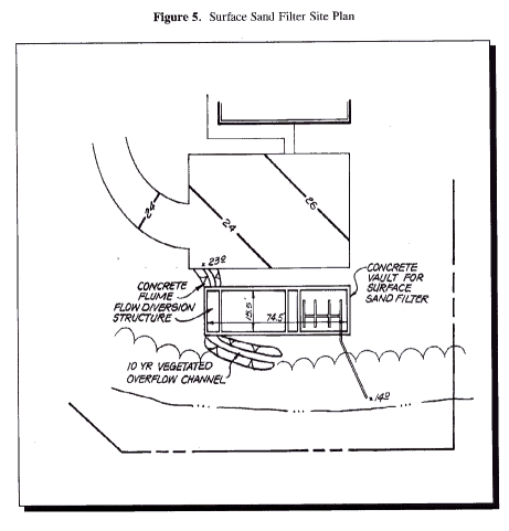
See Figure 5 for Site Plan View.
