stormwatercenter.net · printed Jul 14, 2026
Dry Swale Design Calculator
A dry swale is the most engineered member of the open-channel family: a vegetated channel with a prepared soil bed and an underdrain that filters the entire water quality volume instead of merely conveying it. The calculator above sizes the channel geometry, storage and check dam layout; the guide below covers the terminology (swale, bioswale, ditch — they are not synonyms), the design criteria, and a fully worked two-fork example. The companion dry swale fact sheet covers applicability and performance in depth.
What is a swale?
A swale is a shallow, gently sloped open channel — usually vegetated — that collects and conveys runoff while slowing it down and letting some of it soak in. In a yard, a swale is the subtle grassed dip that steers roof and lawn drainage away from the foundation. In land development, it is a designed conveyance element with a specified cross-section, slope and lining. In stormwater engineering, the word covers a family of treatment practices in which the channel itself does the pollutant removal: grass channels, dry swales and wet swales.
What separates a swale from a pipe is contact: water travels in a wide, shallow sheet through vegetation, which filters solids, slows velocity and promotes infiltration. What separates an engineered swale from a casual ditch is control — computed geometry, a slope held within limits, and erosion checks at every step of the design storm sequence.
Swale vs bioswale vs ditch
The three terms describe points on a spectrum from pure conveyance to pure treatment:
| Feature | Ditch | Swale (grass) | Bioswale / dry swale |
|---|---|---|---|
| Primary job | Move water away, fast | Convey and slow runoff | Filter and treat runoff |
| Shape | Narrow, steep-sided V | Wide, shallow trapezoid or parabola | Wide trapezoid over engineered bed |
| Subsurface | Native soil, often eroding | Native soil | Prepared soil media + gravel + underdrain |
| Vegetation | Incidental | Dense turf | Turf or planted landscape over media |
| Water quality role | None — can be a pollutant source | Partial: surface filtering | Full water quality volume filtered through the bed |
| Standing water | Frequent puddling | Drains with the storm | Designed to empty within 48 hours |
The dividing line that matters to a reviewer: a ditch is sized to a peak flow, a treatment swale is sized to a volume and checked against peak flows.
Types of swales: grass channel, dry swale, wet swale
State manuals split the open-channel group into three practices, and only two of them earn full water quality credit:
- Grass channel — a flat-sloped turf channel sized by velocity rather than volume. Cheapest of the three and the least reliable remover (median TSS removal about 68%), so it is usually credited as pretreatment ahead of another practice rather than as stand-alone treatment.
- Dry swale — the subject of this calculator. The channel stores the water quality volume behind check dams and filters it through a 30-inch engineered soil bed into an underdrain. Monitored performance is the best of the group: median removal around 93% TSS, 83% total phosphorus and 92% total nitrogen.
- Wet swale — a channel that intercepts the shallow water table and holds standing wetland cells. Suited to poorly drained C and D soils where a dry swale’s bed would not drain, at the cost of weaker phosphorus removal and occasional nuisance complaints near residences.
Which one fits a given site is exactly the screening question the BMP selector automates: drainage area, soils, slope, water table and space, scored across all sixteen practices.
Dry swale design criteria
The criteria below recur across state manuals; the calculator enforces them as it sizes the channel.
| Parameter | Criterion | Why |
|---|---|---|
| Contributing drainage area | ≤ 5 acres | Larger areas drive erosive velocities and braiding |
| Bottom width | 2–8 ft | Narrower starves treatment area; wider invites a braided low-flow channel |
| Side slopes | 2:1 max, 3:1+ preferred | Flatter slopes add wetted perimeter and are mowable |
| Longitudinal slope | 1–4% | Below 1% the channel drains poorly; above 4% flow erodes (use check dams or drop structures) |
| Ponding depth (WQv) | ≤ 18 in at the downstream end, ~12 in mid-cell | Keeps vegetation alive and people safe |
| Drawdown time | ≤ 48 hours | Aerobic bed, no mosquitoes, ready for the next storm |
| Soil media depth | 30 in engineered mix | Filtration and pollutant sorption capacity |
| Underdrain | 4–6 in perforated pipe in gravel | Guarantees drawdown on any native soil |
| Water table separation | ≥ 2 ft below the bed | Keeps the filter unsaturated and protects groundwater |
| 2-yr / 10-yr storm | Non-erosive velocity / safe conveyance with ~6 in freeboard | The swale is still a drainage channel |

Soil media and underdrain
The bed is the treatment plant. Native soil is excavated and replaced with a 30-inch engineered mix of sand, topsoil and organic matter — permeable enough to pass the stored volume within the drawdown window, sorptive enough to bind metals and phosphorus. The standard sizing assumption caps the media’s percolation contribution at a conservative rate (the worked example uses 1.5 inches per day) so the design never depends on optimistic soil performance.
Beneath the media sits a gravel layer with a perforated underdrain, typically 4 to 6 inches in diameter, discharging to the storm drain system. The underdrain is what makes a dry swale work on C and D soils where infiltration practices are off the table — and it is also what makes the practice acceptable for hotspot runoff, since filtered water is collected and conveyed rather than infiltrated to groundwater. Keep the bottom of the gravel at least 2 feet above the seasonally high water table.
Check dams
On any slope above the bare minimum, the water quality volume will not sit still on its own. Check dams — low stone, timber or concrete barriers across the channel — break the swale into a stair of level cells, each ponding up to the 18-inch limit at its dam. The geometry is mechanical: each dam creates a ponded wedge reaching upstream a distance of dam height divided by channel slope, so an 18-inch dam on a 1.25% slope backs water 120 feet. Dams need a stable notch or weir for overflow (a small V-notch passes low flows without erosion), protected toes, and at least the 2-year flow depth of clearance above their crests so larger storms pass without flanking them.
Worked example: a two-fork dry swale
The sequence below condenses the design example built into the calculator: a dry swale treating runoff from a community center site, required to provide recharge, treat the water quality volume, and pass the 2- and 10-year storms without eroding. Site data: existing ground at the outlet 22.0 ft, seasonally high water table 13.0 ft, silt loam (ML) soils, adjacent creek invert 12.0 ft.
Step 5 is the step designers get wrong by intuition: the storage that counts is the wedge-shaped volume below the ponding line along the whole channel, not the full prism. Average depth (9 in here) is roughly half the maximum — size with the average, check with the profile.
Vegetation
The grass is structural. A dense, water-tolerant, salt-tolerant turf — the worked example specifies K-31 tall fescue — provides the surface filtering, keeps the bed from sealing, and armors the channel against the velocities the erosion checks assume (the Manning’s n of 0.03 used in the example is a property of healthy tall grass, not bare earth). Establish vegetation with erosion control matting before the swale goes online, and re-seed bare patches as routine maintenance. Where a more landscaped look is wanted, deeper-rooted native plantings over the same media work — that is the bioswale presentation of the same engineering.
Residential drainage swales
The same geometry scales down to lot drainage. A residential swale steering runoff between houses follows the identical rules of thumb: wide and shallow beats narrow and deep, side slopes a mower can handle (3:1 or flatter), at least 1% fall so water never stands, and a stable outlet — a street gutter, a storm inlet or a rain garden, never the neighbor’s foundation. A simple grass swale over native soil is usually enough at lot scale; the engineered bed and underdrain earn their cost when a reviewer requires treatment credit or the soils are heavy clay. Concrete-lined swales appear where space is tight and slopes are steep, trading all treatment value for hydraulic capacity. How streets, lots and drainage elements fit together is the subject of the better site design section.
Maintenance — and when swales fail
Dry swale upkeep is landscape maintenance with a purpose: mow to 3–4 inches, remove trash, clean the forebays and the area behind check dams as sediment accumulates, and re-seed bare soil promptly. Inspect after large storms in the first year, then annually — the single most telling observation is standing water more than 48 hours after rain, which means the surface or the media is sealing and needs cultivation or replacement of the top layer. A wider inspection framework, including the maintenance agreements reviewers expect, is in the maintenance guide.
The failure modes are predictable. Construction-phase sediment is the classic killer — a swale that receives runoff from unstabilized soil clogs before it ever operates, so keep it offline until the drainage area is stabilized. Compaction by construction traffic destroys the bed’s permeability. Undersized or unprotected check dams erode at the toe and flank at the edges. Concentrated inflows without pretreatment cut gullies through the bottom. And mowing scalped too low, or not at all, removes the vegetative armor the hydraulic design depends on. Every one of these is cheaper to prevent in specification than to repair in year two.
Performance and cost
Monitored dry swales post the best numbers of any open channel practice — median removals of about 93% for TSS, 83% for total phosphorus and 92% for total nitrogen, with study-to-study variability documented in the pollutant removal database. Cost scales with the engineered bed: early estimates put construction at roughly $5.50 per cubic foot of water quality volume treated (Brown and Schueler, 1997) — several times a simple grass channel, but typically cheaper than vault-based filters, and partially offset where the swale replaces curb-and-gutter and storm pipe. For a pond-scale comparison on larger sites, see the stormwater pond design calculator.
Frequently asked questions
What is a swale?
A swale is a shallow, gently sloping vegetated channel that collects, slows and conveys stormwater runoff while letting part of it filter into the ground. Engineered versions add specified geometry, controlled slopes and sometimes a filter bed to turn the channel into a treatment practice.
What is a swale drain?
“Swale drain” is the everyday name for a drainage swale — a graded surface channel that moves water by gravity instead of through a pipe. Some include a buried perforated pipe (an underdrain or French drain) beneath the turf to handle what the surface flow leaves behind.
What is a swale in landscaping?
In landscaping, a swale is a shaped depression that doubles as drainage and design feature — often planted, mulched or dressed with river stone. It directs roof and surface water away from structures and toward a lawful discharge point or infiltration area.
What is a drainage swale?
A drainage swale is any open channel graded to convey runoff — the broadest of the swale terms. It becomes a treatment practice only when designed to hold and filter a water quality volume, as a dry swale does.
What is a swale in construction?
On a construction site, a swale is a graded channel shown on the drainage plan to intercept and route runoff — sometimes temporary, for erosion control during construction, sometimes a permanent stormwater element built to the criteria on this page.
What is a swale in a yard?
A yard swale is the shallow grassed dip — often barely noticeable — that carries water from downspouts and lawn toward the street or a drainage easement. Keeping it unobstructed and at a continuous 1%+ fall is most of what residential drainage maintenance amounts to.
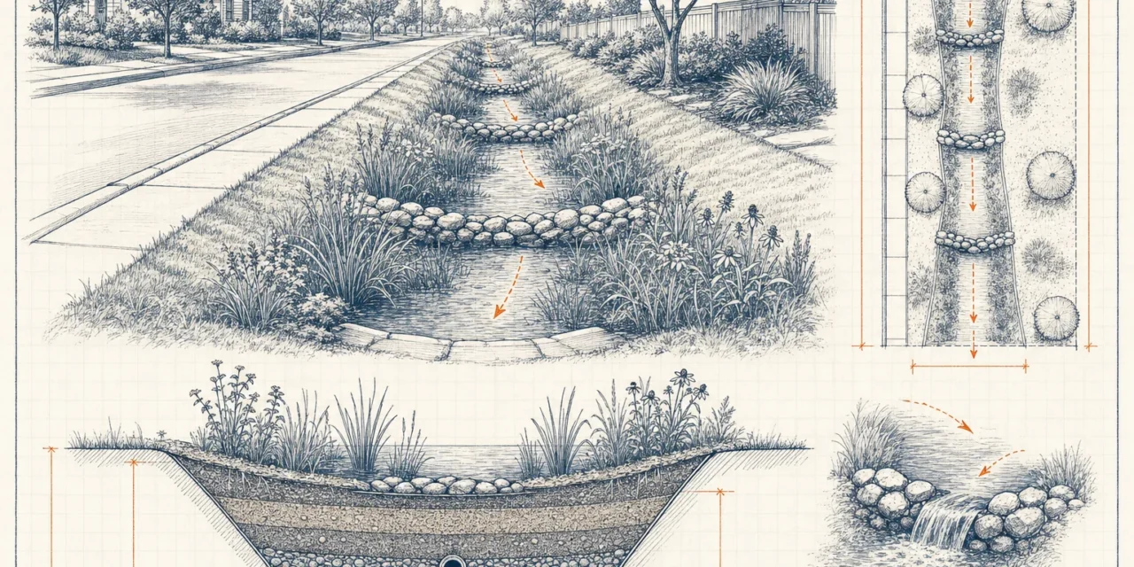
What does a swale look like?
Like a wide, shallow grassy valley rather than a ditch: a flat or gently rounded bottom 2 to 8 feet across, side slopes gentle enough to mow, and depth measured in inches rather than feet. Engineered swales may show low stone check dams crossing the channel at regular intervals.
What is the difference between a swale and a bioswale?
A bioswale is a swale with an engineered filter bed — soil media, often a gravel layer and underdrain, and planted vegetation. Civil engineering manuals call the same configuration a dry swale. A plain swale conveys and slows runoff; a bioswale is additionally sized to filter the water quality volume through its bed.
What is the difference between a swale and a ditch?
Shape and intent. A ditch is narrow and steep-sided, sized only to move water away quickly, and often erodes. A swale is wide and shallow, sized to slow water down, hold it briefly and filter it through vegetation — geometry that also makes it safer and easier to maintain.
What is a swale ditch?
An informal term for a roadside channel that splits the difference — typically an existing ditch regraded wider and flatter so it behaves like a swale. Converting ditches to dry swales is a common retrofit because the right-of-way already exists.
What are the different types of swales?
Three engineered types: the grass channel (conveyance with partial treatment), the dry swale (engineered bed and underdrain, full treatment, drains dry), and the wet swale (intercepts the water table and holds standing wetland cells). Each has its own fact sheet on this site.
How do you properly design a swale?
Fix the layout and slope (1–4%), choose a trapezoidal section with a 2–8 ft bottom and 3:1 side slopes, size the section so the water quality volume ponds no deeper than 18 inches behind check dams, verify drawdown within 48 hours, then check the 2-year velocity and 10-year capacity with freeboard. The calculator above runs that exact sequence.
What slope should a drainage swale have?
Between 1% and 4% along its length. Below 1% water stands and the turf drowns; above 4% flow turns erosive and the design needs check dams or drop structures to break the grade into compliant segments.
How deep should a swale be?
Total channel depth of about 2 to 2.5 feet covers most designs: up to 18 inches of treatment ponding plus freeboard for the 10-year storm. The treatment storage itself is intentionally shallow — average ponding depths run well under a foot.
How do you design a wet swale?
A wet swale uses the same channel geometry but is excavated down to intersect the shallow water table, with no media bed or underdrain; check dams form permanent wetland cells planted with emergent vegetation. It suits C/D soils and high water tables — see the wet swale fact sheet.
What are the disadvantages of swales?
They consume linear space, are limited to small drainage areas (about 5 acres) and gentle slopes, can erode or braid if poorly built, and depend on healthy vegetation. Wet swales can raise mosquito and aesthetics concerns near homes, and grassed systems occasionally export bacteria.
Can a swale handle hotspot runoff, like from a gas station?
A dry swale can: the underdrain collects filtered water and conveys it to the storm system instead of infiltrating it, which protects groundwater. Practices that infiltrate directly — and swales without engineered beds — should not receive untreated hotspot runoff.
How long can water stand in a swale after rain?
Design standard is complete drawdown within 48 hours; the worked example drains within 24. Standing water beyond two days signals a clogged surface or failing media and is the trigger for maintenance, not a cosmetic issue.